Pump Theory
The following diagrams show the Pump Theory and Design system.
Click the thumbnails below or the left and right arrows on the diagrams to navigate.
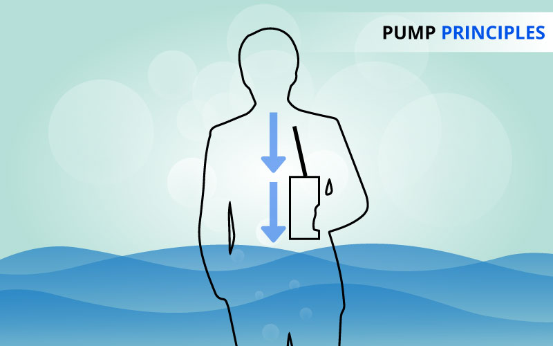
1. All pumps use basic forces of nature to move a liquid. As the moving pump part (impeller, vane, piston diaphragm,etc.) begins to move, air is pushed out of the way. The movement of air creates a partial vacuum (low pressure) which can be filled up by more air, or in the case of water pumps, water. This is similar to sucking on a straw. A partial vacuum is created in your mouth when you suck on the straw. The liquid is pushed up the straw because of the pressure differences between your mouth and the atmosphere.
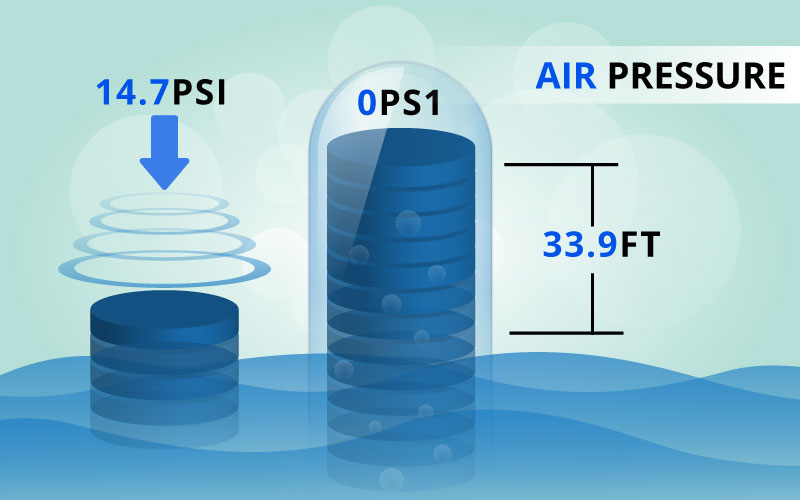
2. At sea level, mother nature exerts a pressure of 14.7 psi all around us. If one end of a tube is placed in water and a perfect vacuum is applied to the other end, that 14.7 psi could hold a column of water 33.9 feet high. This is only obtainable at sea level and with a perfect vacuum. In reality, ALL centrifugal pumps can lift water no more than 26 feet at sea level. This drops off approximately 2 feet for each 1000 feet of altitude above sea level.
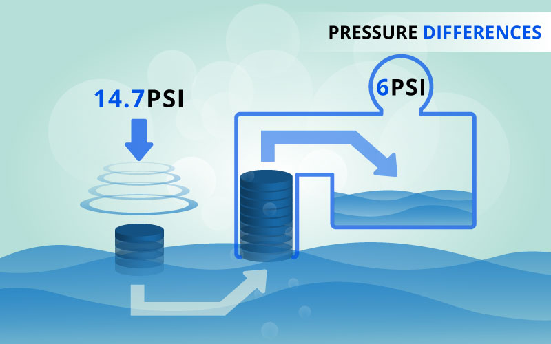
3. In nature, movement is from more dense to less dense. Weather systems are tracked as high pressures move toward low pressures. In batteries, one end contains more positively charged particles that move to the end with the negatively charged particles. A liquid under high pressure will move to an area of less pressure if a path is provided.
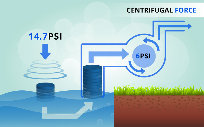
4. The centrifugal pump works in the same way as sucking on the straw. As the engine starts, the impeller turns which forces the water around it out of the pump's discharge port. The partial vacuum created, allows the earth's air pressure to force water up the suction hose (straw), and into the suction (inlet) side of the pump to replace the displaced water. When the water hits the rotating impeller, energy of the impeller is transferred to the water, forcing the water out (centrifugal force). The water is displaced outward, and more water can now enter the suction side of the pump to replace the displaced water.
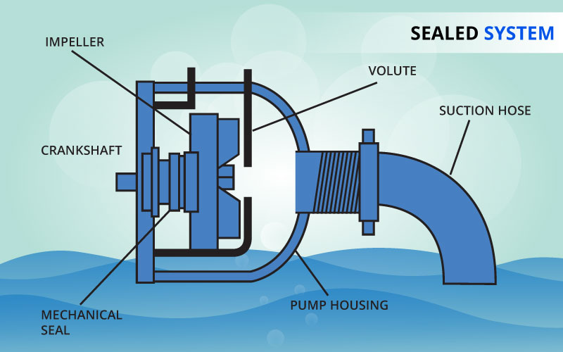
5. If a water pump is to create a partial vacuum in the pump housing, three things must happen:
- The pump must be primed. The water in the housing is essential to lubricate the mechanical seal so that it won't wear and leak.
- The suction hose, hose seals and all O-rings must be in good condition so air can't be drawn in, losing the vacuum.
- The impeller-to-volute clearance must be within specification to achieve the proper vacuum.
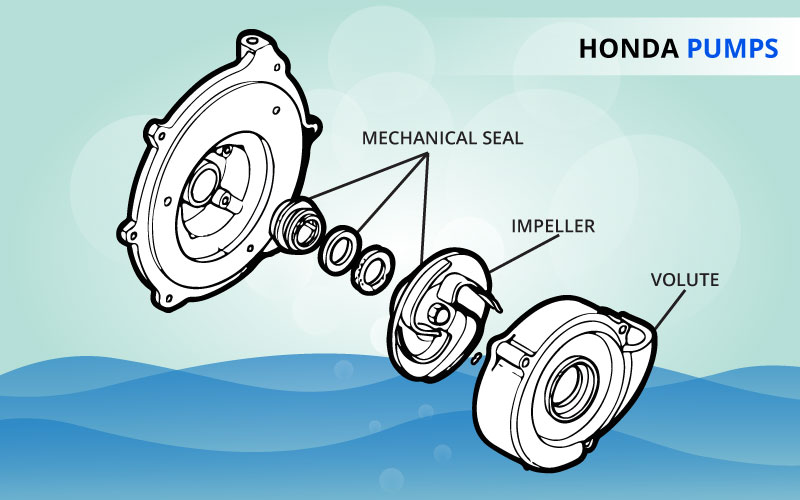
6. The size of the impeller and its vanes dictate what pressures, discharge capacities and types of material that can pass through the pump. The impeller material,and the size of the volute discharge opening, determine what size material can pass through the pump without damaging it.
STANDARD (WX, WB Series)Deeper vanes will produce a larger discharge capacity.
HIGH-PRESSURE (WH Series)A larger diameter impeller with more, shallower vanes will produce a greater pressure.
TRASH (WT Series)Deepest vanes produce largest discharge capacity. Deeper vanes, incorporated with a large volute discharge opening, will pass larger debris without harming the pump components.
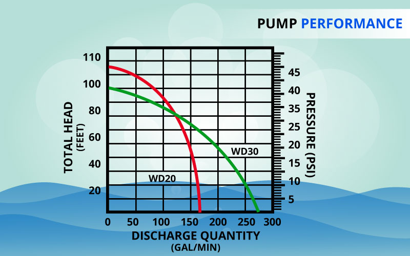
7. The performance curves reflect standard testing. Pump manufacturers typically calculate performance curves using a pressure gauge and a flow meter connected to the discharge port. For any anticipated total head, the discharge capacity can be determined. Pump performance curves can be found on each model page.
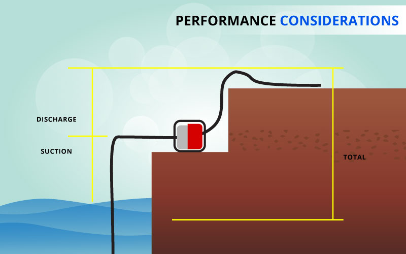
8. The performance curves are useful in selecting a particular water pump. When a question regarding the performance of a specific pump must be answered, refer to the pump specifications for the particular model.
Determine how high the pump will sit above the water source (static suction head). Determine how high the discharge end will be elevated above the pump (static discharge head). Determine what the discharge capacity (gpm) of the pump must be.
Given the total head (suction + discharge), the discharge capacity can be estimated by referring to the performance curve.
Keep in mind, the actual discharge performance may be significantly less than predicted by using static head alone because of friction losses in the system.
Pressure can be calculated for total head by multiplying total head by .433. Pressure available at the end of the hose at zero flow for a given total head (less then the maximum total head) can be calculated by multiplying the total head by .433 then subtracting it from the maximum pressure.
Example: The maximum pressure for a WH20X is 71 psi (.433 x 164 total head in feet). The maximum available pressure at a total head of 120 feet is 71 - 52 (120 x .433) = 19 psi at zero flow.
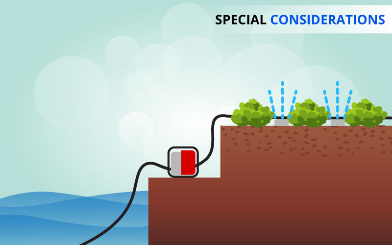
9. The total static head is often only considered when selecting a pump. However, because of frictional losses, this method can often lead to large error, and in many cases, the pump performance will not meet expectations. The selection process becomes even more complicated when a nozzle or sprinklers are used.
In order to accurately predict the performance of a centrifugal pump in a specific application, the total head losses must be considered. These losses include, but are not limited to: total static head, losses due to pipe size, length, and material, and losses due to sprinklers or a nozzle.
Accurately predicting the discharge and pressure for a given pump in a specific application requires tedious calculations and a lot of trial and error.
Honda offers Pump Select® software to make the difficult calculations for you.
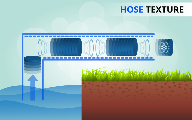
10. Another fact of nature, is that a liquid moving through a hose creates heat due to the friction of the two surfaces (water against hose). Steel pipe will produce more friction than will smooth PVC or vinyl pipe. Friction INCREASES with INCREASED length of pipe, or hose, or smaller diameter hose, and will DECREASE the discharge capacity (GPM).
The roughness of the hose/pipe is considered in Pump Select® calculations.
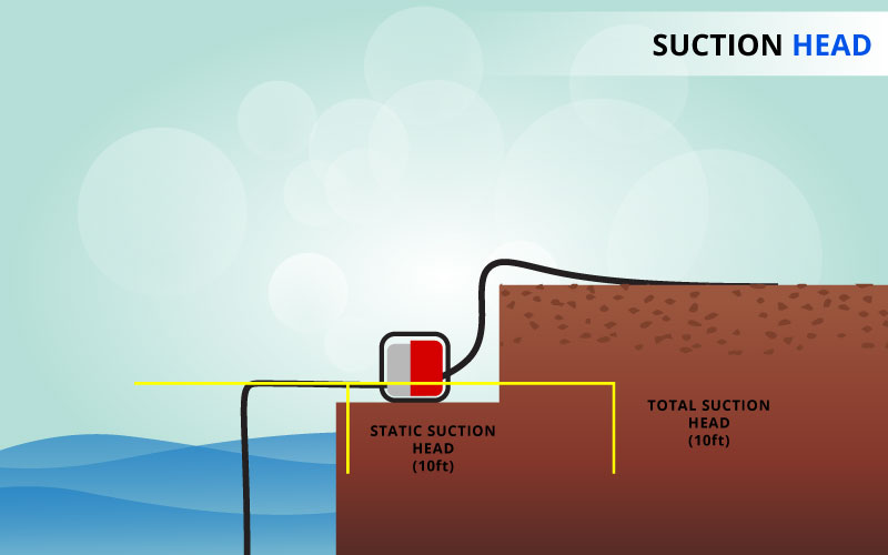
11. Mother nature plays an important role by exerting only 14.7 psi on any body of water at sea level. This limits the suction head of centrifugal pumps to 33.9 feet. However, this would only be obtained if we could achieve a perfect vacuum in the pump. In reality, the suction head of centrifugal pumps is limited to about 26 feet. Pump performance (capacity or pressure) is highest when the pump is operated close to the water's surface. Increasing the suction head will DECREASE the discharge head and consequently the discharge capacity of the pump. Most importantly, suction head should be kept to the smallest value possible to reduce the likelihood of cavitation. Cavitation can also occur if the suction hose is restricted. Never use a suction hose with a smaller diameter than the suction port. Cavitation can quickly damage a pump.
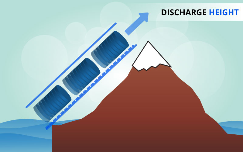
12. Mother nature plays an important role in how high we can push water. Water is heavy; about 8.3 lbs per gallon. The old saying,"what goes up, must come down" tends to want to bring the water back down to its source. The mechanical energy of the impeller transmits its force against the water coming in contact with it. This force can be measured in psi at the pump discharge. As the pump discharge head increases in height, the pump capacity (gpm) decreases and the available pressure at the end of the discharge hose (if the flow is stopped or a sprinkler/nozzle is used) will also decrease. At maximum head, the capacity (gpm) will drop to zero and there will be no pressure available at the end of the hose to run a sprinkler or nozzle. If we measured the pressure at the bottom of the discharge hose, we would read maximum head pressure which would be the result of the pump supporting the water weight. The performance curves show the relationship between discharge capacity and total head.
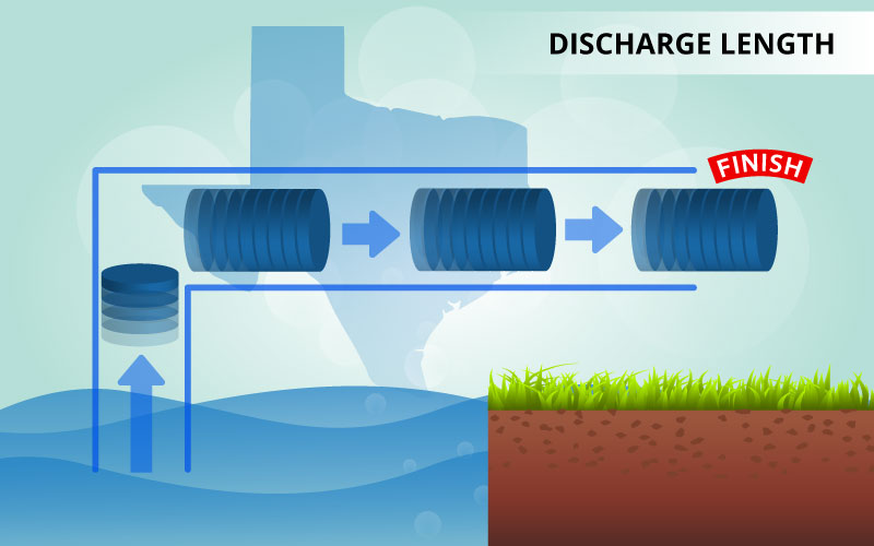
13. As the length of the discharge hose increases, the water comes into contact with more hose surface. As discussed in hose material, the inner wall of the discharge hose (in contact with the rushing water) will cause friction to build up. The increase in friction will slow the water, decreasing the discharge capacity.
Hose/pipe length is considered in Pump Select® calculations.
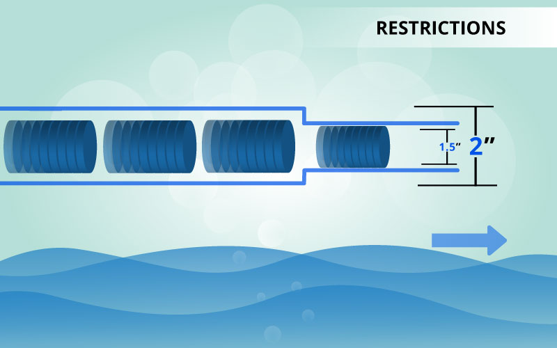
14. Restrictions are like dams to the flow of water. When the water hits the restriction, only a partial amount of the flowing water will be allowed to pass through. A rule of thumb is to keep the discharge hose as straight as possible and avoid reducing the size of the hose whenever possible. Restrictions will INCREASE the friction and DECREASE the discharge capacity at the end of the pipe.
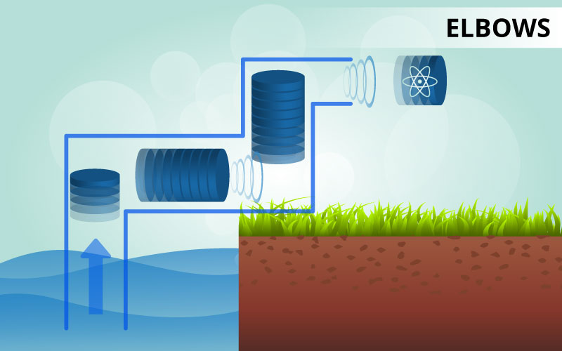
15. Elbows added to lengths of pipe break up the smooth flow of the water. The turbulence created around these joints causes an increase in friction which will DECREASE the discharge capacity.
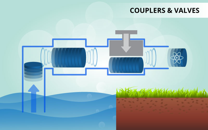
16. As valves and couplers are added to lengths of pipe, the smooth flow of the water is broken up. The turbulence created around these joints causes an increase in friction which will DECREASE the discharge capacity.
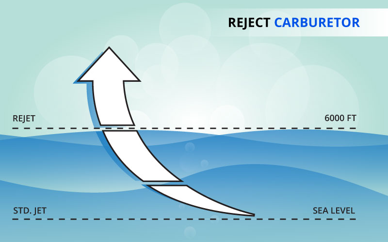
17. Engine performance DECREASES with altitude. The higher the altitude, the less air there is available to support combustion. Maximum engine power DECREASES about 3.5% per 1000 feet of altitude.
Less air also means there is less air pressure to push on the body of water we are trying to draw into the pump. Because there is less air pressure forcing the water into the pump, the maximum available suction head is DECREASED. The reduction in engine power may also result in a reduced discharge capacity.
 Pump Principles
  Atmospheric Pressure
 Pressure Differences
 Centrifugal Force
  Sealed System
 Pump Type Differences
 Pump Performance
 Pump Considerations
 Special Considerations
 Discharge Material vs Performance
  Suction Head vs Performance
 Discharge Head vs Performance
 Discharge Length vs Performance
 Restriction vs Performance
 Elbows vs Performance
 Couplers and Valves
 Altitude vs Performance


